
Converting UTM Coordinates to Latitude/Longitude
QUESTION: I have a GeoTIFF image in a UTM projection. And I can calculate the corners and center of the image in UTM coordinates from the data file. I am trying to geolocated this image so I can put political boundaries and grid lines on it, but to do so I need to create the proper UTM map projection space. If I read the MAP_PROJ_INIT documentation correctly, I seem to need the center of the map projection in latitude and longitude values in order to set up the map projection structure. But I can't work out how to get there from what I have in the GeoTIFF file. Can you help?
![]()
NOTE: A different (and much simpler) treatment of this topic can be found in this article.
![]()
ANSWER: I am going to presume you have read the article Overlaying Geographic Data on GeoTIFF Images that describes how to set up a data coordinate space in UV coordinates so you can overlay political boundaries and grid lines on your image. I won't go into that here. It seems to me your basic problem stems from not knowing how to set up the UTM map projection in the first place, without using the center latitude and center longitude to do it. I can understand your confusion, because I was similarly confused the first time I read the documentation.
In fact, it is probably easier than you expected it to be. The first thing you need to know is that UTM coordinates is just another name for UV coordinates. That is to say, UTM coordinates are coordinates on a rectilinear grid, in which the grid spacing is in meters. This is the usual case with UV coordinates, too.
Here is a slightly edited version of the GeoTIFF dump of the metadata available in the GeoTIFF file. The output was obtained from running listgeo, as described in the previous article.
    Geotiff_Information:       Version: 1       Key_Revision: 1.0
      Tagged_Information:          ModelTiepointTag (2,3):
            0                0                0
            162150.75        9070030.75       0
         ModelPixelScaleTag (1,3):
            28.5             28.5             0
         End_Of_Tags.       End_Of_Geotiff.     PCS = 32718 (name unknown)
   Projection = 16118 ()    Projection Method: CT_TransverseMercator
      ProjNatOriginLatGeoKey: 0.000000 (  0d 0' 0.00"N)
      ProjNatOriginLongGeoKey: -75.000000 ( 75d 0' 0.00"W)
      ProjScaleAtNatOriginGeoKey: 0.999600
      ProjFalseEastingGeoKey: 500000.000000 m
      ProjFalseNorthingGeoKey: 10000000.000000 m    GCS: 4326/WGS 84
   Datum: 6326/World Geodetic System 1984
   Ellipsoid: 7030/WGS 84 (6378137.00,6356752.31)
   Prime Meridian: 8901/Greenwich (0.000000/  0d 0' 0.00"E)
   Corner Coordinates:    Upper Left    (  162150.750, 9070030.750)
   Lower Left    (  162150.750, 8947480.750)
   Upper Right   (  262043.250, 9070030.750)
   Lower Right   (  262043.250, 8947480.750)
   Center        (  212097.000, 9008755.750)
This information is duplicated, in a harder to read way, in your GeoTIFF file and can be obtained via the GEOTIFF keyword in READ_TIFF. Be sure you reverse the Y dimension of your image after you read it. This is almost always necessary when working with TIFF files in IDL.
    file = '300601N_DOS3B_B1.tif'
   image = Read_Tiff(file, GEOTIFF=geotag)
   image = Reverse(image, 2) ; Necessary for TIFF files.
   Help, geotag, /Structure
      ** Structure, 7 tags, length=88, data length=82, refs=1:
         MODELPIXELSCALETAG     DOUBLE    Array[3]
         MODELTIEPOINTTAG       DOUBLE    Array[6, 1]
         GTMODELTYPEGEOKEY      INT              1
         GTRASTERTYPEGEOKEY     INT              1
         GEOGLINEARUNITSGEOKEY  INT           9001
         GEOGANGULARUNITSGEOKEY INT           9102
         PROJECTEDCSTYPEGEOKEY  INT          32718
In particular, you can discover that this image is projected in a UTM coordinate system in zone 18 in the Southern Hemisphere. The PROJECTEDCSTYPEGEOKEY geotag is translated as 327xx, where 327 means Southern Hemisphere (326 means Northern Hemisphere), and the xx is translated as the zone. So, zone 18 in the Southern Hemisphere. This particular code also means that the datum used for the projection is WGS84. (I looked this information up on the GeoTIFF web reference pages.)
Please note that UTM projections that use the WGS84 datum in IDL produce incorrect results. To produce correct results in versions of IDL prior to IDL 8.2, when the problem is scheduled to be fixed, you must switch to the Malbeck datum. The Malbeck datum is essentially the same as the WGS84 datum. In practice, we use a datum index of 12, rather than 8. This is done automatically for you if you use the Coyote Graphics map projection routines.
From the previous article, you know that the UV coordinates are in meters (GEOGLINEARUNITSGEOKEY geotag), and you can calculate the corners of the image from the tie points and the pixel scale factors, like this.
   ; Find the image dimensions. Will need to find corners.
   s = Size(image, /Dimensions)
   ; Calculate corner points from GeoTIFF structure obtained from file.
   xscale  = geotag.ModelPixelScaleTag[0]
   yscale  = geotag.ModelPixelScaleTag[1]
   tp      = geotag.ModelTiePointTag[3:4]
   ; Origin in upper-left in TIFF file. I want to move to bottom left
   ; for my own sanity.    xOrigin = tp[0]    yOrigin = tp[1] - (yscale * s[1])
   xEnd = xOrigin + (xscale * s[0])    yEnd = tp[1]
   xCenter = (xEnd - xOrigin) / 2.0 + xOrigin
   yCenter = (yEnd - yOrigin) / 2.0 + yOrigin
The trick now is to set up a UTM map projection, so you can easily inversely transform the corner and center points you calculated in UV space into latitude and longitude space. This is easy to do without using the CENTER_LATITUDE and CENTER_LONGITUDE keywords that the documentation for MAP_PROJ_INIT seems to imply.
We simply use the ZONE keyword, taking care to give it a negative value to indicate that this is a Southern Hemisphere zone. (Northern Hemisphere zones are indicated with positive values.) Once this is done, we can use MAP_PROJ_INVERSE to convert any point or points we like in UV coordinates to their latitude/longitude equivalents. In this case, we can convert the image corner points and the center of the image.
     ; Map the corners in lat/lon space.
    utmMap = MAP_PROJ_INIT('UTM', DATUM=12, ZONE=-18)
    lonlat = MAP_PROJ_INVERSE([xOrigin, xOrigin, xEnd, xEnd,    xCenter], $
                              [yOrigin, yEnd,    yEnd, yOrigin, yCenter], $
                               MAP_STRUCTURE=utmMap)
We can now print out the values of the image corners, starting at the lower-left and proceeding clockwise. The center of the image is also printed out.
    IDL> Print, 'Latitude:  ', Reform(lonlat[1,0:3])
    IDL> Print, 'Longitude: ', Reform(lonlat[0,0:3])
           Latitude:    -9.5080335  -8.4011585  -8.4071821  -9.5148641
           Longitude:   -78.076767  -78.067467  -77.161038  -77.167596
    IDL> Print, 'Center: (', lonlat[0,4], ',' , lonlat[1,4], ')'
           Center: (-77.618174, -8.9580965)
The rest of the code is nearly identical to what you saw in the Overlaying Geographic Data on GeoTIFF Images article. We simply calculate a limit from the corners of the image, and use that to create a map projection structure. We obtain the UV_BOX, which is used to set up a data coordinate system for the overlay from MAP_PROJ_INIT. (See the previous article if you don't understand why this is the case.)
   ; The limit is the min and max of these latitudes and longitudes.
   minLat = Min(lonlat[1,*], MAX=maxLat)
   minLon = Min(lonlat[0,*], MAX=maxLon)
   limit = [minLat, minLon, maxLat, maxLon]
   ; Set up a map projection space, using a limit. The map coordinate will
   ; get its position from the image.
   utmMap = Obj_New('cgMap', 'UTM', DATUM=12, ZONE=-18, LIMIT=limit, /ONIMAGE)
          ; Set up color table.    cgLoadCT, 0
   ; Scale the image for better viewing.
   scaled = BytScl(image, MIN=0.020, MAX=0.065)      ; Display the image.
   cgDisplay, 700, 860    cgImage, scaled, POSITION=pos, /KEEP_ASPECT
   ; Set up the data coordinate space.    utmMap -> Draw
   ; Put the world on top
   cgMAP_CONTINENTS, /HIRES, Color='Powder Blue', Map_Structure=utmMap,  /RIVERS
   ; Add gridlines
   cgMAP_GRID,/LABEL, Color='Indian Red', Map_Structure=utmMap
The final result is shown in the figure below. It does look to me as if the river in the upper right corner is out of its channel a bit, but I suspect this had more to do with inaccurate river coordinates than it does with the map projection. To confirm this, I would try to find a file with more confirmed geological data for this region of Peru.
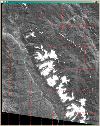 |
| The GeoTIFF image with geographic features added. |
To confirm that we have done the map projections correctly, you could try entering the center of the image and its corners, specified in latitude/longitude units, into any of the UTM to Lat/Lon converters available on the Internet and see if you don't get back to the UTM (or UV) coordinates of your image.
![]()
Copyright © 2008 David W. Fanning
Last Updated 18 November 2011