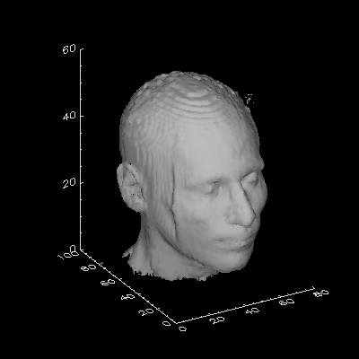
Adding Axes to a Rendered 3D Volume
QUESTION: How can I add appropriate axes to a rendered isosurface or 3D volume?
![]()
ANSWER: The key to doing this properly is to do the rendering in the Z-graphics buffer. I like to use the SURFACE command with the NoData keyword set to draw the axes. Be sure to use the Save keyword to save the 3D transformation matrix in the !P.T system variable. The transformation matrix is then used with the PolyShade command to render the isosurface in the 3D space. (Note that the PolyShade command normally returns a 2D array, but that this behavior is changed in the Z-buffer so that the 3D volume is rendered directly.)
Here is an annotated example program that shows you how it is done. Click here to download the example program itself. Note that the program uses IDL 5 function calls (although not for the rendering or axes placement).

PRO VolAxes, data, isolevel, XRange=xrange, YRange=yrange, $
   ZRange=ZRange, Exact=exact

   ; This is an example program to show how to place axes on
   ; a rendered 3D iso-surface. It uses the HEAD.DAT data file
   ; distributed with IDL if no data is passed. This program
   ; uses IDL 5 functionality.

On_Error, 1

   ; Get demo data set if necessary.

IF Arg_Present(data) EQ 0 THEN BEGIN

   filename = Filepath(Subdirectory=['examples','data'], $
      'head.dat')
   OpenR, lun, filename, /Get_Lun
   data = BytArr(80, 100, 57)
   ReadU, lun, data
   Free_Lun, lun

ENDIF

   ; Get size of data set.

s = Size(data)
IF s(0) NE 3 THEN Message, 'Data must be 3D. Returning...'
xmax = s(1)
ymax = s(2)
zmax = s(3)

   ; Default parameter values.

IF Arg_Present(isolevel) EQ 0 THEN isolevel = 35
IF Arg_Present(xrange) EQ 0 THEN xrange = [0, s(1)]
IF Arg_Present(yrange) EQ 0 THEN yrange = [0, s(2)]
IF Arg_Present(zrange) EQ 0 THEN zrange = [0, s(3)]
exact = Keyword_Set(exact)

   ; Open a window for displaying the data.

Window, /Free, Title='Volume Rendering with Axes', $
   XSize=400, YSize=400

   ; Save device name and number of colors.

thisDevice = !D.Name
ncolors = !D.N_Colors

   ; Do the isosurface rendering in the Z-Buffer.

Set_Plot, 'Z'
Erase
Device, Set_Resolution=[400,400], Set_Colors=ncolors

   ; Draw the axes with the SURFACE command. Save T3D.

Surface, Dist(30), /NoData, XRange=xrange, YRange=yrange, $
   ZRange=zrange, /NoErase, /Save, XStyle=exact, $
   YStyle=exact, ZStyle=exact

   ; Render the isosurface.

Shade_Volume, data, isolevel, v, p, /Low
image = PolyShade(v, p, /T3D, XSize=400, YSize=400, Top=ncolors)

   ; Take a "snapshot" of the display window.

snapshot = TVRD()

   ; Display the snapshop in the display window.

Set_Plot, thisDevice
TV, snapshot
END
![]()
Running the code above should produce output like this.
![]()
Last Updated 1 June 1997

