
Warping a Map Projected Image
QUESTION: I have data in two different map-projected grids (images). I would like to compare the two data sets. Can you show me how to use IDL to convert one map-projected grid to the other?
![]()
ANSWER: Yes, let me give you an example. I have data from an over-flight experiement conveniently saved in a GeoTiff file. The data (an image) was gridded using a UTM map projection with a WGS 84 ellipsoid as the datum. I have other data, collected at the same time, from the MODIS instrument on the Terra satellite. This data has been gridded onto a Lambert Azimuthal Equal Area projection, with a sphere of radius 6371228 meters as the datum. I would like to see if there is enough overlap between these two images to use them in a comparison study. The GeoTiff image is a 10000-by-10000 gridded image. The MODIS image is a 1000-by-1000 image. The center of the image is approximately the same latitude and longitude location in both images.
I have developed a number of programs to work around some of the limitations of IDL's map projection code. I am going to be using these programs in the following example. In particular, I am going to be using a cgMap object to work around the problem of ephemeral map structures and the fact that IDL produces incorrect results when a UTM map projection is used with a WGS84 datum.
The first thing I do is to set up a map coordinate object for the two gridded data sets. Remember that the cgMap object is used is a wrapper for Map_Proj_Init. First, for the GeoTiff image from the first experiment. The Find_Resource_File and cgGeoMap functions are Coyote Library programs. The former finds a file located somewhere in the IDL path, while the latter is used to read a GeoTiff file to create a cgMap coordinate object.
The FindMapBoundary program reads a GeoTiff file, a netCDF file, or a GPD file produced with the GPD_Viewer and will return the boundary (outline) of the gridded area described by the file. The ranges returned by the FindMapBoundary program are just another way of describing the grid boundary (tiffBounds), and are in the XY coordinates of the projected map space.
   tiffFile = Find_Resource_File('overflightstudy.tif')
   tiffCoord = cgGeoMap(tiffFile)
   success = FindMapBoundary(tiffFile, tiffBounds, XRANGE=tiff_xrange, YRANGE=tiff_yrange)
   IF ~success THEN Message, 'Cannot find a grid boundary in the supplied file.'
   tiffCoord -> SetProperty, XRANGE=tiff_xrange, YRANGE=tiff_yrange
Next, I set up a similar cgMap variable for the new study area.
    studyGPDFile = Find_Resource_File('study.gpd')
   studyCoord = Obj_New('cgMap', "Lambert Azimuthal", SPHERE=6371228.0, $
                         CENTER_LATITUDE=90, CENTER_LONGITUDE=0)
   success = FindMapBoundary(studyGPDFile, studyBounds, XRANGE=study_xrange, YRANGE=study_yrange)
   studyCoord -> SetProperty, XRANGE=study_xrange, YRANGE=study_yrange
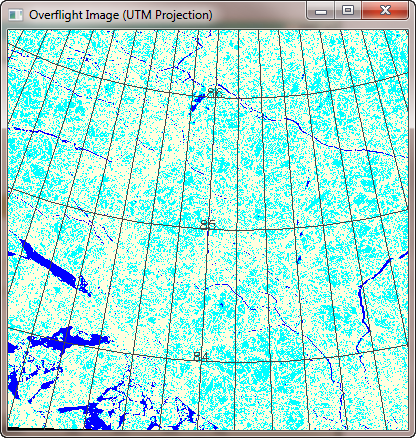
With the map coordinate variables now set up, I can display the two images in their native map projections. First, the overflight image.
    image = Read_Tiff(tiffFile, rr, gg, bb)     TVLCT, rr, gg, bb
    pos = [0, 0, 1, 1]     cgImage, Reverse(image,2), /KEEP_ASPECT, POSITION=pos
    tiffCoord -> SetProperty, POSITION=pos, /Draw
    cgMap_Grid, MAP_STRUCTURE=tiffCoord, LATDEL=1.0, LONDEL=2.5,
       COLOR='charcoal', /LABEL, /BOXAXES, GLINESTYLE=0
Then, the study image.
     cgLoadCT, 4, /BREWER
    pos = [0, 0, 1, 1]
    cgImage, BytScl(studyImage), /KEEP_ASPECT, POSITION=pos
    studyCoord -> SetProperty, POSITION=pos, /Draw
    cgMap_Grid, MAP_STRUCTURE=studyCoord, LATDEL=1.0, LONDEL=2.5, $
       COLOR='charcoal', /LABEL, GLINESTYLE=0
You can see the two images in the figure below. The study image appears to be rotated about 90 degrees from the overflight image.
 |
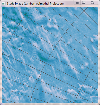 |
| The overflight image in UTM projection on left and the study image in Lambert Azimuthal projection on the right. | |
What I wanted to do was see the study image warped into the same map grid as the overflight image. I thought I could use Map_Proj_Image to do this kind of warping for me. I had a great deal of trouble at first, until I realized that the Map_Proj_Image documenation was leading me astray. In particular, the Limit parameter to Map_Proj_Image (the second positional parameter) was described in terms of latitude and longitude values, and it should have been described in terms of XY boundary values. (The documentation has been fixed in IDL 7.1.2, but the machine I was using at work was IDL 7.0.1 and had older documentation.) Eventually, I reasoned that the Limit parameter had to work with XY coordinates or I didn't know a damn thing about map projections, so I tried it and everything worked exactly as I was expecting it to work!
The command I used looked like this. The IMAGE_STRUCTURE keyword requires the map structure for the study image (the image I am warping), while the MAP_STRUCTURE keyword requires the map structure of the overflight image (the map projection I am warping the image to).
    warped = Map_Proj_Image(studyImage, studyBounds, $
             IMAGE_STRUCTURE=studyCoord->GetMapStruct(), $
             MAP_STRUCTURE=tiffCoord->GetMapStruct(), $
             MISSING=!Values.F_NAN, UVRANGE=uvOut)     pos = [0, 0, 1, 1]
    cgImage, BytScl(warped, /NAN), /KEEP_ASPECT, POSITION=pos
    tiffCoord -> SetProperty, POSITION=pos, XRANGE=uvOut[[0,2]], YRANGE=uvOut[[1,3]], /Draw
    cgMap_Grid, MAP_STRUCTURE=tiffCoord, LATDEL=1.0, LONDEL=2.5, $
        COLOR='charcoal', /LABEL, GLINESTYLE=0
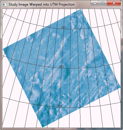
You can see in the figure below how the study image has been warped into the overflight image grid. The original study image is shown on the right so you can compare it to the rotated image.
 |
|
| The study image (on the left) warped into the map projection grid of the overflight image. The original study image is on the right for comparison. | |
Notice that the study image only covers about half of the original overflight image grid. Here is a blended image view that shows the two images together. In this case, the best idea is to regrid the MODIS study data using a GPD file and map projection that more closely resembles the original overflight data. This is especially so because we were most interested in the features in the lower-left corner of the overflight images, which are barely covered by the study image.
Blendimage, overflightImage, warpedStudyImage, Alpha=0.25
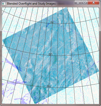 |
| The overflight and study image blended together for better comparison. |
![]()
Take Care Warping TIFF Images
In the course of doing this work, I discovered an important point about warping TIFF images with Map_Proj_Image. Namely, that it is absolutely essential to reverse the TIFF image before passing it to Map_Proj_Image for warping. It is not possible to read the TIFF image, pass that to Map_Proj_Image, and then display the warped image (reversed or not) in the proper orientation.
For example, here is a TIFF image in its native UTM coordinate system, displayed with grid lines. Note the round feature in the lower-right hand part of the image, with a latitude line of 84.870 passing through its center.
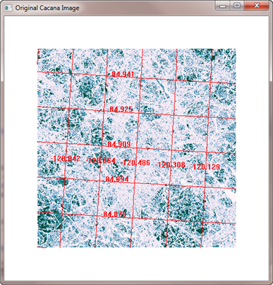 |
| A TIFF image in native UTM projection. |
One might be tempted to read the image, warp it, and display it with commands similar to these:
    tiffCoord = cgGeoMap(tiffFile)
   success = FindMapBoundary(tiffFile, tiffBounds, XRANGE=tiff_xrange, YRANGE=tiff_yrange)
   tiffCoord -> SetProperty, XRANGE=tiff_xrange, YRANGE=tiff_yrange
   leaCoord = Obj_New('cgMap', "Lambert Azimuthal", SPHERE=6371228.0, $
                       CENTER_LATITUDE=90, CENTER_LONGITUDE=0)
   image = Read_Tiff(tiffFile, rr, gg, bb)
   warped = Map_Proj_Image(image, tiffBounds, $
       IMAGE_STRUCTURE=tiffCoord->GetMapStruct(), $
       MAP_STRUCTURE=leaCoord->GetMapStruct(), $
       MISSING=!Values.F_NAN, UVRANGE=uvout)    pos = [0,0,1,1]
   cgImage, BytScl(warped, /NAN), /KEEP, POSITION=pos
   leaCoord -> SetProperty, POSITION=pos, XRANGE=uvout[[0,2]], YRANGE=uvout[[1,3]]
   grid = Obj_New('cgMapGrid', MAP_OBJECT=leaCoord, COLOR='red', linestyle=0, /AUTODRAW)
   grid -> Draw
You see the results in the figure below.
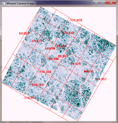 |
| A TIFF is read, warped, and displayed without reversing the image. Note completely incorrect grid locations on the image! |
The result at first looks correct, but pay careful attention to the grid lines overlayed on the image. They are completely in the wrong place on the image! (Compare with the original image.)
You might think, "Oh, well, I forgot to reverse the image for display." But just making that simple change to the cgImage command in the code above makes things even worse.
cgImage, Reverse(BytScl(warped, /NAN),2), /KEEP, POSITION=pos
Now the grid doesn't even align with the image!
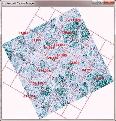 |
| Reversing the warped image makes things worse. |
The only way to do this correctly is to reverse the image when it is read out of the TIFF file, and use the reversed image as input to Map_Proj_Image. The code looks like this.
    tiffCoord = cgGeoMap(tiffFile)
   success = FindMapBoundary(tiffFile, tiffBounds, XRANGE=tiff_xrange, YRANGE=tiff_yrange)
   tiffCoord -> SetProperty, XRANGE=tiff_xrange, YRANGE=tiff_yrange
   leaCoord = Obj_New('cgMap', "Lambert Azimuthal", SPHERE=6371228.0, $
                       CENTER_LATITUDE=90, CENTER_LONGITUDE=0)
   image = Read_Tiff(tiffFile, rr, gg, bb)
   warped = Map_Proj_Image(Reverse(image,2), tiffBounds, $
       IMAGE_STRUCTURE=tiffCoord->GetMapStruct(), $
       MAP_STRUCTURE=leaCoord->GetMapStruct(), $
       MISSING=!Values.F_NAN, UVRANGE=uvout)    pos = [0,0,1,1]
   cgImage, BytScl(warped, /NAN), /KEEP, POSITION=pos
   leaCoord -> SetProperty, POSITION=pos, XRANGE=uvout[[0,2]], YRANGE=uvout[[1,3]]
   grid = Obj_New('cgMapGrid', MAP_OBJECT=leaCoord, COLOR='red', linestyle=0, /AUTODRAW)
   grid -> Draw
You see the correct results in the figure below.
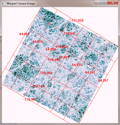 |
| Correct results from Map_Proj_Image only by reversing the TIFF image before the image is warped. |
It is extremely difficult to tell if an image has been warped properly unless you can see grid lines on top of the image to confirm the warping has been done correctly.
![]()
Version of IDL used to prepare this article: IDL 7.1.2
![]()
Copyright © 2010 David W. Fanning
First Written 28 February 2010
Updated 20 November 2011