
Placing an Image on a Surface
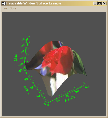
QUESTION: I can't quite make out how to add an image as a texture map to an object graphics surface. I keep getting errors. Can you show me now to do this?
![]()
ANSWER: Well, you don't follow the recommendations in the IDL documentation. :-)
Editor's Note: As of 27 Novemember 2010 you can place an image on the surface as a texture map automatically, using the Texture_Image keyword to FSC_Surface.
The proper way to do this is to add the image (as an image object) to the surface with the Texture_Map keyword. But to make it work correctly, you also have to use the Texture_Coords keyword. Reading the IDL documentation for the Texture_Coords keyword will lead you astray, since it implies that if you want the image to completely cover the surface you should set the texture map keyword to a value like this:
texcoords = [[0,0], [1,0], [1,1], [0,1]]
In fact, if you try that you get this error message.
% IDLGRSRCDEST::DRAW: Error, numbers of vertices, normals, and
   texture coordinates do not match.
What you really have to do is create a texture map coordinate for each grid box in the surface. In other words, if your surface data is in a 40 by 50 array, your texture map coordinates will be a 2 by 40 by 50 array.
One way to create the proper texture map coordinates is like this:
      s = Size(surfaceData, /Dimensions)
      texcoords = FltArr(2, s[0], s[1])
      texcoords[0,*,*] = (Findgen(s[0])#Replicate(1,s[1])) / (s[0]-1)
      texcoords[1,*,*] = (Replicate(1,s[1])#Findgen(s[0])) / (s[0]-1)
Then the image can be added to the surface object with code similar to this:
   thisImage = Obj_New('IDLgrImage', image)
   thisSurface = OBJ_NEW('IDLgrSurface', surfaceData, x, y, Style=2, $
      Color=[255,255,255], Texture_Map=thisImage, Texture_Coord=texcoords
I have written an example program, named Texture_Surface, that shows you what this looks like. You can run the program like this:
IDL> Texture_Surface
The program, with it's default values, is shown in the figure below.
![]()
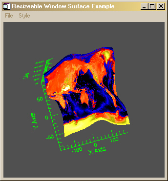
Of course, you can pass your own surface data and image to the program. For example, you could do this (if you had the cgDemoData and cgScaleVector programs from my web page):
   IDL> wave = cgDemoData(3)
   IDL> x = cgScaleVector(Findgen(41), -180, 180)
   IDL> y = cgScaleVector(Findgen(41), -90, 90)
   IDL> world = cgDemoData(7)
   IDL> Texture_Surface, wave, x, y, Image=world, Colortable=5, /Exact
The results are shown in the figure below.
![]()
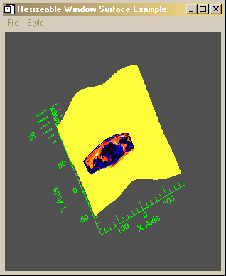
It is also possible to place the image on just a portion of the surface. For example, there is a Position keyword to Texture_Surface that can be used to locate the image on a portion of the surface. The Position keyword is a four-element array that gives the lower-left X coordinate, the lower-left Y coordinate, the upper-right X coordinate, and the upper-right Y coordinate of the position on the surface, respectively.
For example the wave data set described above is a 41 by 41 array. Suppose we wish to put the image with its lower-left corner at (5,10) and its upper-right corner at (25,18) with respect to this surface. Then we can call Texture_Surface like this:
   IDL> wave = cgDemoData(3)
   IDL> x = cgScaleVector(Findgen(41), -180, 180)
   IDL> y = cgScaleVector(Findgen(41), -90, 90)
   IDL> world = cgDemoData(7)
   IDL> Texture_Surface, wave, x, y, Image=world, Colortable=5, $
          /Exact, Position=[5, 10, 25, 18]
The program is shown in the figure below. Notice that the rest of the surface is yellow in this instance. I've seen it other colors as well. For example, try calling the program like this to see yet another color.
IDL> Texture_Surface, Position=[5, 10, 25, 18]
I haven't yet figured out where this surface color comes from, or how to make it a color of my own choosing. There also seems to be a problem around the edges (especially the right edge) of the image. I've convinced myself that my coordinates are correct, so I don't understand the source of this problem either. I continue to look into it.
The algorithm that calculates the texture coordinates with the Position keyword defined looks like this:
   s = Size(surfaceData, /Dimensions)
   texcoords = FltArr(2, s[0], s[1])
   texcoords[0,position[0]:position[2],position[1]:position[3]] = $
     (Findgen(position[2]-position[0]+1) # $
      Replicate(1,position[3]-position[1]+1)) / (position[2]-position[0])
   texcoords[1,position[0]:position[2],position[1]:position[3]] = $
      (Replicate(1,position[3]-position[1]+1)) # $
      Findgen(position[2]-position[0]+1) / (position[2]-position[0])
![]()
The day after I first posted this article, Karl Shultz, from Research Systems responded to these unresolved issues in an IDL newsgroup article. Here is the complete article.
   Subject: Re: texture_coord
   From: Karl Schultz
   Date: Fri, 2 Nov 2001

   "David Fanning" (david@dfanning.com) wrote ...

   Note that the article talks about a couple of unresolved
   issues. First, when I position the image as above, I don't
   seem to have control over what color the *rest* of the
   surface is.

   Yes, that's a little hard in this context.  In fact, my difficulty in
   explaining this may suggest that we need to add something to IDL to make
   this easier.  Some discussion may help.

   At least with the code posted in this thread, we were just letting the
   "unused" texture coords stay (0,0), which means that the color on the rest
   of the surface would take on the color of the (0,0) texel, whatever that is.
   See next topic.

   Second, the positioned image seems to have
   problems around its edges. I suspect both of these problems
   may be related, but so far I have made no progress resolving
   them. I'm open to any and all ideas.

   Right.  I noticed this too.  There's some interpolation going on along the
   edge of the surface.  One thing to keep in mind is that there isn't always
   an one-to-one relationship between texels and pixels.  It may take several
   texels to decide what color to make a pixel, as is the case where the
   texture has a higher sampling than the screen.  Or, a single texel may be
   used to determine the color of many pixels in the opposite case.  You might
   be seeing texel (0,0) and the texel from an edge of the texture being
   combined to determine the color of a pixel along the edge.  This can lead to
   somewhat random-looking results.

   In fact, the texel interpolation is a whole lot worse than this.  Suppose
   that you are mapping a texture onto a sub-surface with corners [20,20] and
   [30,30].  The texture coordinate at [20,20] is [0,0].  The texture
   coordinate at [20,19] is also [0,0], so there is no real problem there.  But
   if you look at the texture coordinate at [28,20] and at [28,19] we see that
   two adjacent texture coords are something like [0.9,0.0] and [0.0,0.0].
   This is really bad because OpenGL will take all the texels (from the image)
   between (normallized) [0.9,0.0] and [0,0], average them together, and then
   use that color value as one of the colors used to decide the color of the
   pixel in that area.  It gets a lot worse if you go over to [30,30] where we
   would average all the image texels in a diagonal line across the image.
   Yuk. OpenGL is doing what we tell it to, but not what we want.

   OpenGL has a LOT of facilities in its texture mapping support to control
   border issues, which indicates to me that it is not a simple problem.  IDL
   doesn't expose all these controls.

   One step in attacking the problem is to pre-process your image to put a
   border around it.  Make the color whatever you'd like the "rest" of the
   surface to look like.  And you might try it with one-pixel borders, and
   perhaps two or three.  I extended your program (texture_surface) to do this
   and I got a nice black background since I made my borders black.

   But this didn't completely solve the problem.  The left and the bottom
   borders look ok - black.  But the top and right edges have smudged up colors
   where the black border should be.  This is caused by the texel interpolation
   across the image I mentioned above.  How to fix this?  More work.  The
   texture coords of the vertices ADJACENT to the area where the texture is
   mapped need to be something other than [0,0].  Using the above example
   again, the texture coordinates at [28,20] should be [0.9,0.0] and the
   texture coordinates at [28,19] need to be [0.9,0.0] as well.  This will
   cause the texels accessed from the image to be the same (the new border
   texels in this case) and we should get black.  In fact, it may make sense to
   set the texture coords at [28,0:19] to [0.9,0.0].  This avoids the
   [0.9,0.0]->[0.0,0.0] texel interpolation across the image.

   I also tried this with your program and got pretty encouraging results,
   although I didn't implement a full, general solution. Maybe I'll work on it.

   The bottom-line is that we were getting lazy by not setting the texture
   coordinates of the vertices of the "rest" of the surface to reasonable
   values.  This caused a major discontinuity in the texture interpolation.

   Oh, by the way, I think I was wrong about the resolution
   of the surface. Making the surface bigger does not seem
   to affect the resolution of the image on the surface
   at all.

   I almost posted about this topic yesterday.  Right, the number of polygons
   (facets) in the surface won't have an effect on the appearance of the image.
   The texture image is interpolated across each facet, using the texture
   coords of the facet to determine what part of the image is used.  If you
   generate more facets, you will have smaller steps in the texture coordinates
   across the facets and you end up with the same thing.  If you wanted to do
   something other than a linear texture mapping, like some sort of morphing,
   then you might want more facets to give you more control.

   You may see some difference in a more geometric sense.  For example, if you
   have an implicit surface (generated by some function) that is pretty curvy,
   you'll get a better looking and more accurate surface as you increase the
   number of facets, texture or no texture.  For simpler surfaces, fewer facets
   suffice, textured or not.  People often map textures onto 4-vertex planar
   polygons or surfaces so that they can display an image in a more flexible
   way.  You can't really manipluate an IDLgrImage very well with all the model
   transforms, so if you wanted to display an image with an arbitrary
   transform, you can map it onto a simple polygon and orient it however you
   want.  You also gain a lot of functionality in the areas of stretching and
   transparency.  Anyway, one facet is enough if all you want is a flat
   surface.  The image texels are interpolated across the single facet.
![]()
I incorporated Karl's suggestions into Texture_Surface. Karl originally suggested a two-pixel border around the image to get the surface color around the image correct. But I was worried about placement artifacts this might create, so I implemented a one-pixel border. I found this works in every case I have tried, but it has not been tested exhaustively.
You can set the surface color with a BorderColor keyword. Set the value to a RGB color triple. For example, to set the surface to a light gray color, try this:
IDL> Texture_Surface, Position=[10, 5, 35, 30], BorderColor=[185, 185, 185]
The results are shown in the figure below.
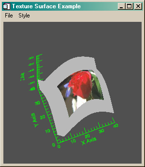
Note that this figure also incorporates Karl's suggestions for improving the resolution about the edges of the image. The actual algorithm used looks like this:
IF N_Elements(position) NE 0 THEN BEGIN

      ; Normal texcoords positions.

   texcoords = FltArr(2, s[0], s[1])
   texcoords[0,position[0]:position[2],position[1]:position[3]] = $
     (Findgen(position[2]-position[0]+1) # $
      Replicate(1,position[3]-position[1]+1)) / (position[2]-position[0])
   texcoords[1,position[0]:position[2],position[1]:position[3]] = $
      (Replicate(1,position[3]-position[1]+1)) # $
      Findgen(position[2]-position[0]+1) / (position[2]-position[0])

      ; Extend texcoords in unused areas to prevent interpolation problems
      ; at image boundaries.

      ; Bottom (and Y for LL and LR corners).

   texcoords[0,position[0]:position[2],0:position[1]-1] = $
      (Findgen(position[2]-position[0]+1) # $
       Replicate(1,position[1])) / (position[2]-position[0])
   texcoords[1,*,0:position[1]-1] = 0.0

      ; Top (and Y for UL and UR corners).

   texcoords[0,position[0]:position[2],position[3]+1:*] = $
      (Findgen(position[2]-position[0]+1) # $
       Replicate(1,s[1]-position[3]-1)) / (position[2]-position[0])
   texcoords[1,*,position[3]+1:*] = 1.0

      ; Left (and X for LL and UL corners).

   texcoords[0,0:position[0]-1,*] = 0.0
   texcoords[1,0:position[0]-1,position[1]:position[3]] = $
      (Findgen(position[3]-position[1]+1) # $
       Replicate(1,position[0])) $
       / (position[3]-position[1])

      ; Right (and X for LR and UR corners).

   texcoords[0,position[2]+1:*,*] = 1.0
   texcoords[1,position[2]+1:*,position[1]:position[3]] = $
      (Findgen(position[3]-position[1]+1) # $
       Replicate(1,s[0]-position[2]-1)) / (position[3]-position[1])

ENDIF ELSE BEGIN
   texcoords = FltArr(2, s[0], s[1])
   texcoords[0,*,*] = (Findgen(s[0])#Replicate(1,s[1])) / (s[0]-1)
   texcoords[1,*,*] = (Replicate(1,s[1])#Findgen(s[0])) / (s[0]-1)
ENDELSE
![]()
I note that placement of the image on the surface can look a bit rough, depending upon the aspect ratio of the surface, the aspect ratio of the image, and the position chosen for placement. (The placement on the image in the figure above was chosen for its pleasing aesthetic qualities, not for its scientific accuracy.) I'm not sure these problems can be overcome without extensive trial and error. :-(
![]()
Copyright © 1997-2001 David W. Fanning
Last Updated 4 November 2001