
Working with Transparent Images and cgImage


QUESTION: I realize cgImage has a Transparent keyword that can be used to set the transparency of an image when it is displayed, but I really don't understand the purpose or role of the various transparency keywords that are available in cgImage, or even how such transparency can be used. Can you fill me in on some of the details?
![]()
ANSWER: Yes, of course, I have been confused about how this all works myself. Recently, I sat down to modify cgImage a bit and see if I couldn't figure it out and make sense of the various keywords. This is my current understanding of how transparency works in cgImage. You will need a current version of cgImage to perform the examples below.
First of all, to create a transparent image, you have to have two 24-bit images and a function, usually called the alpha channel, that tells you how to combine the two images together to make a single image. The two images we are going to use are called the background image and the foreground image. In practice, the background image is almost always the current contents of the display window, and the foreground image is the image we are trying to display in the display window with transparency.
When you issue a cgImage command that requires transparency, if you don't provide a background image via the AlphaBackgroundImage keyword, cgImage will copy the contents of the current display window into a 24-bit color image. (It uses cgSnapshot to do this.) It is impossible to this kind of copying if you are in the PostScript device, which is why it is mandatory to supply this background image via the AlphaBackgroundImage keyword if you want to use transparency in the PostScript device.
If the foreground image is a 2D image, rather than the required 24-bit image, then cgImage will also construct a 24-bit image out of the 2D image and the color table vectors that will be used to display the image.
So far, so good. Now, we have the two 24-bit images we need. It is simple to construct an alpha channel from the value of the Transparent keyword. The alpha channel just tells us what percentage of color should come from one of the images, as opposed to the other. If the Transparent keyword is set to 30, for example, then 30 percent of the color comes from the background image, and 70 percent comes from the foreground image.
All that is left to do, is to blend the two images together and display the blended image in the display window. This is where things get a little complicated with the keywords available in cgImage.
Mostly for historical reasons, and to keep the size of the images reasonable, the blending of the images is done in the Z-graphics buffer. This buffer is created to be the same size as the current graphics window (or, in the case of the PostScript device, to have the same aspect ratio as the current graphics window). The AlphaBGPos keyword, which is set to [0,0,1,1] by default, is used to locate the background image in the Z-graphics buffer window. I would say 99.9 percent of the time there is absolutely no reason to use this keyword! I would probably remove it, except that the very first person besides me who used the Transparent keyword with cgImage had a requirement for it. Go figure.
The AlphaFGPos keyword (also set to [0,0,1,1] by default) is used to locate the foreground image in the Z-graphics buffer. This is the keyword you want to use to locate the transparent image in the graphics display window. Sometimes you don't use this keyword, but it is set to the proper value for you. This is what happens, for example, if you use the Overplot and Transparent keywords together. The Overplot keyword sets the Position keyword, or in the case of a transparent image, the AlphaFGPos keyword to the proper location, based on the previously established axis range in the graphics window.
Once the background and foreground images have been displayed in the Z-graphics buffer, a snapshot of the window is taken, and this is the blended image that is now to be displayed in the original graphics window. It is displayed in the location given by the Position keyword, which is also set to [0,0,1,1] by default.
![]()
Examples of Transparent Images
All this is best learned by example, however, so let's try a couple of things.
First, we will just display a background image and a transparent foreground image on top of it. We'll use the world image and the CT scan image from the IDL demo directory as examples, but these could be any images at all. Both of these images are 2D images.
   cgDisplay, 500, 500
   cgImage, cgDemoData(7), CTIndex=0
   cgImage, cgDemoData(5), CTIndex=33, Transparent=30
You see the result in the figure below.
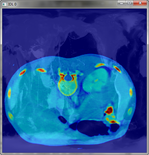 |
| A transparent image displayed directly on top of another image. |
This may not be what you had in mind. The CT scan image has a lot of black pixels in it, where there is no data. These black pixels are also interacting with the background image. It would be better to make these pixels completely transparent. We can do this with the Missing_Value keyword, like this. You see the new result below the code.
   cgDisplay, 500, 500
   cgImage, cgDemoData(7), CTIndex=0
   cgImage, cgDemoData(5), CTIndex=33, Transparent=30, Missing_Value=0
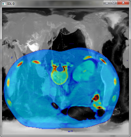 |
| The same image, but with the Missing_Value keyword set to make missing values completely transparent. |
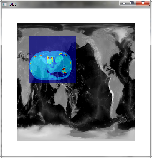
If you wanted to position the CT scan image at a particular location in the display window, you would use the AlphaFGPos keyword to do so. Let's position this image in the upper right quadrant of the display.
   cgDisplay, 500, 500
   cgImage, cgDemoData(7), CTIndex=0
   cgImage, cgDemoData(5), CTIndex=33, Transparent=30, Missing_Value=0, $
        AlphaFGPos=[0.5, 0.5, 1.0, 1.0]
 |
| The same image, but positioned in the upper right quadrant of the display. |
Please note that if you had used the Position keyword instead of the AlphaFGPos keyword in the code above, cgImage would have assigned the AlphaFGPos keyword the Position values and reassigned the Position to be [0,0,1,1]. This is because this is the only thing that makes sense in this scenario. A warning message would have been issued.
   IDL> cgDisplay, 500, 500
   IDL> cgImage, cgDemoData(7), CTIndex=0
   IDL> cgImage, cgDemoData(5), CTIndex=33, Transparent=30, Missing_Value=0, $
        Position=[0.5, 0.5, 1.0, 1.0]
   % CGIMAGE: POSITION keyword value switched to ALPHAFGPOS because TRANSPARENT keyword is set.
Also note that the Transparent keyword can sometimes be set without you actually setting it. For example, if you use either the Missing_Value or Missing_Color keyword, the Transparent keyword will be set (unless the Missing_Index keyword is also used), because these operations can only be carried out with transparent images. These commands are identical to the commands above, if the Transparent keyword was set to zero.
   cgDisplay, 500, 500
   cgImage, cgDemoData(7), CTIndex=0
   cgImage, cgDemoData(5), CTIndex=33, Missing_Value=0, Position=[0.5, 0.5, 1.0, 1.0]
![]()
Overplotting Transparent Images
Transparency is perhaps most useful when you want to position an image on top of another image, using the coordinates of the two images to do the positioning. This is the role of the Overplot keyword in cgImage.
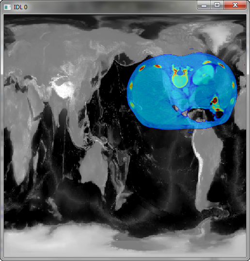
All that is required is that you save the coordinates of the first image when you display it. For example, let's display our first image using coordinates that go from 0 to 500 in both X and Y. Then we will position the second image at location 50 to 250 in X and 250 to 450 in Y. The code looks like this.
   cgDisplay, 500, 500
   cgImage, cgDemoData(7), CTIndex=0, XRange=[0,500], YRange=[0,500], Margin=0.1, /Save
   cgImage, cgDemoData(5), CTIndex=33, Transparent=30, $
      XRange=[50,250], YRange=[250,450], /Overplot
Note that in this case, you don't want to specify either the Position or the AlphaFGPos keywords, since these will be set correctly by the Overplot keyword itself. You see the results in the figure below.
 |
| Use the Overplot keyword to position
the transparent image using the coordinates of the two images. |
I find the Overplot keyword is especially useful when I want to overlap two map projected images. You can either specify the map projection information with the MapCoord keyword to cgImage, or if your images are in GeoTiff files, cgImage can read the map coordinates directly from the GeoTiff file. For example, here is how I use cgImage to display a LandSat image on top of a zone classification image, both of which are in GeoTiff files.
  zoneFile = 'zones.tif'
  landSatFile = '19820725_241_069_b7.tif'
  cgImage, Filename=zoneFile
  cgImage, Filename=landSatFile, Stretch=1, MinValue=0, MaxValue=16, $
     Transparent=10, CTIndex=0, Missing_Value=0, /Overplot
You see the result in the figure below.
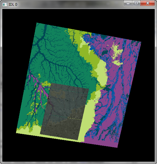 |
| A LandSat image (in gray) displayed with
transparency on a zone image, both in GeoTiff files. |
![]()
Version of IDL used to prepare this article: IDL 8.2.
![]()
![]()


